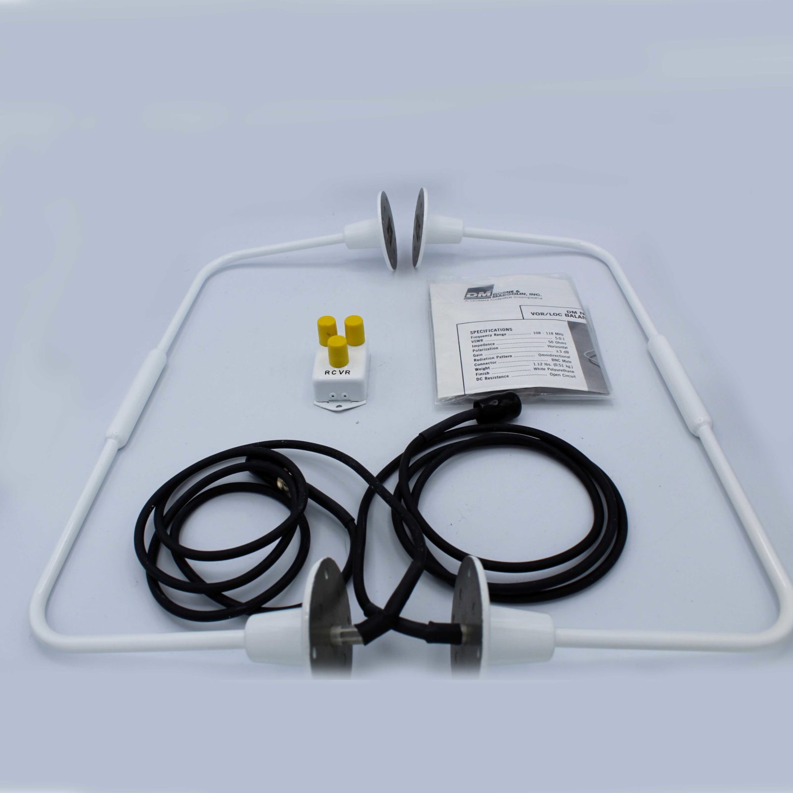
Vor Antenna Aircraft - Do you remember the VOR service limits? How to avoid negative thoughts? Here's what you need to know about how VORs work for your next flight.
The VHF Omni Directional Range Radio (VOR) is the most common surface navigation aid (NAVAID) you use. VOR modeling allows you to fly side-to-side on defined flight paths between VORs. The VOR station is as follows:
Vor Antenna Aircraft

Although some VORs are being phased out slowly by the FAA, there are still hundreds of VORs around the country. These are important sources of international flight status information, instrument charts, and can help you quickly find your location if you get lost.
Localizer And Vor Antenna Question
The VOR range is 108.0 MHz to 117.95 MHz. Each VOR is oriented to magnetic north (more on that later) and radiates 360 radials from the station. A VOR sends one main signal and one variable signal. These sections are called the "reference" and "change" sections.
The aircraft's VOR antenna, usually located on the tail, picks up this signal and transmits it to a receiver inside the aircraft. The aircraft's VOR compares the difference between the variable and the reference part of the VOR and stabilizes the aircraft from the station. This indicator is the radial that the aircraft is currently operating on.
Most VORs have mass measuring equipment (DME) or navigational aids (TACAN) installed in the VOR station. When VOR and DME are combined, they are labeled "VOR-DME". On the other hand, when VOR and TACAN are combined, it is called VORTAC. You can find them classified into VFR Sectional Charts, IFR Low Charts, IFR High Charts, SIDs, STARs and Instrument Approaches. VOR signals are like this:
Most VORs have DME, and if they do, you can tell how far you are from the station using a readout display on your aircraft.
Piper Arrow Iv Turbo For Sale
VORs are limited by line of sight. Obstacles, terrain, and even the slope of the ground interfere with VOR signals. There is no limit to the number of aircraft that can use a VOR at the same time. There are three classes of VORs: Terminal (T), Low (L), and High (H). You can look up the VOR in the FAA Chart Supplement to find out which area it is.
The farther you are from the VOR, the higher you have to fly to get a signal. This is why the VOR provides volume of service at the lower end of the range depending on the geography and curvature of the earth.
Swayne is a director, certified flight instructor and First Officer on the Boeing 757/767 for a major American airline. He graduated from the University of North Dakota in 2018 with a degree in aviation, holds a PIC Type Rating for Cessna Citation Jets (CE-525), is a former pilot for Mokulele Airlines, and flies Embraer 145s in the beginning of his aviation career. Swayne writes stories, quizzes and lists every week. You can connect with Swayne at @swayne and follow his flying adventures on his YouTube channel. A vertical ground plane mounted next to the anchorage. Notice how the side of the fuselage (ground plane) descends almost immediately to a vertical position. This will seal the ground areas properly.

Last month we had a short general discussion about antennas. Let's be more specific about what we need to do to get a good antenna.
Vor/loc/gs Antenna Choice
In the absence of GPS and ADF, all antennas on the plane are ground planes or dipoles. A ground plane antenna has a single element that is positioned at 90 degrees above an infinity that is directed in all directions. The dipole antenna consists of two linear elements (pen-flat) far from any conductor. This is the theory.
Ground or dipole antenna elements can be made in any vehicle, usually metal. The best metals are (in order) silver, copper, gold, aluminum, zinc, nickel, copper, and bronze. In fact, the difference between a silver antenna and a copper antenna is so small that sensitive equipment is needed to tell the difference. On the plane, you really can't tell the difference. Use whatever iron works best for you.
The author has a copper ribbon dipole antenna on a wooden dowel. Note that the antenna is fed in the middle. Also note that there appear to be two bay feed lines connected to the hose. This is the coax balun, which we will talk about next month.
Let's do it now. In a plane, the plane cannot be made on an infinite surface. We usually limit "infinite space" to antennas built on the earth (the first "space" was Marconi's "ground plane" and it is used for radio broadcasting, etc.). Even an aluminum plane is not "endless", but it works like that in the first way. This often works for us.
Cobham Comant Ci 120 200g/s L Vor/gs Antenna At Skygeek.com
A true "ground plane" antenna has no radiation below the plane; all radiators are away from and above ground. Consider a donut dropped from above onto a vertical element. It will be very difficult to talk to a place on the ground from an airplane, because the entire signal will go up into space (except for the top - the "hole in the donut" effect). However, the plane of the ground on the plane is not perfect, and if you think about the shape of the fuselage, you will notice that it is quite a bit pointing down and down. So, an antenna that uses the body as a ground plane will have more radiation to the sides and down, which is what we want.
The author's personal editor holds a brass insert inside a radome (plastic water pipe). This will be a vertical mount antenna that uses the right and left hand buttons of the controller.
And the dipole does not want to form on the metal. Its signal is on the broad side of the dipole, and the vertical dipole emits a high signal on the horizon. Think of a donut that slides over one of the elements and moves down to cover the center of the dipole; there will be maximum radiation at right angles to the dipole, but there will be a large hole right at the edge of both elements.

Dipoles are also like "nubed" in the center for iron. The edges are very sensitive to traffic, but you can get away with mounting them up or going through a metal in the middle. It is also true that you can eliminate the "doughnut hole" effect by cooling each element (say, 30 degrees angle) from the horizontal rather than vertical stacking of elements. This makes it look like a very shallow V with the best reception at the open end of the V. This is why most metals look forward to getting "rabbit ears" on the VOR. / LOC horizontal antenna is on the fixed plane. get the best from where you're going, not where you're going.
Aircraft N245sp (2000 Cessna 525a Citationjet Cj2 C/n 525a0006) Photo By Doug Robertson (photo Id: Ac829663)
A horizontal beam VOR/LOC antenna mounted on the vertical stabilizer. This particular antenna will best be found on the back of the plane.
Ground planes and dipoles have a special need to be "flat". This means, especially in a plastic plane, if the elements remain vertical or horizontal, the elements can be bent to match the shape of the plane, especially in the last 25% of the element length.
One thing a dipole needs is a ground plane that isn't a balun (pronounced BAAH-luhn; more on that in a future column).
Let's build a dipole antenna and see what we can think of (the same principles apply to the ground plane).
E's Van's Rv 14a: Antennas: Vor Antenna Installed
What do we get out of it? Copper tops the list because it is cheap and easy to find. What type of copper? I had a question: "Is it worth #40 copper wire hanging on my glass cover?" The answer is yes, but not well. How come?
Radiation patterns of the Earth's atmosphere. Notice the "doughnut hole" just above the plane.
The answer is bandwidth. Copper wire will work well when cutting. It will not be useful in all aspects of time, and the answer is what we call the Voltage Standing Wave Ratio (VSWR - VIZZ-value). In short, the transmitter tries to inject energy into the antenna and radiate it. The VSWR says, "No, I'm getting some of that power back because the antenna and transmitter and coax are not properly aligned." How can this happen?

If you remember last month, we said that the impedance at the center of the resonant dipole is about 70Ω, and the center of the resonant ground plane is half that, about 35Ω. However, we design our transmitters with 50Ω impedance. How come? Because we are
Suggested Ant Placement _rv 7_9 Pg 2b
Vor loc gs antenna, vor loc antenna, vor antenna location, vor glide slope antenna, vor antenna on aircraft, vor antenna, vor antenna design, aircraft vor, aircraft antenna manufacturers, vor antenna installation, vor ils antenna, vor antenna cessna 172
0 Comments